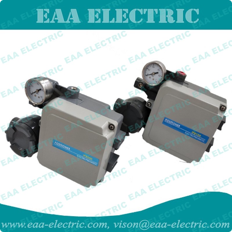
SMC Type Valve Positioner
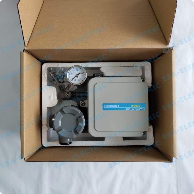
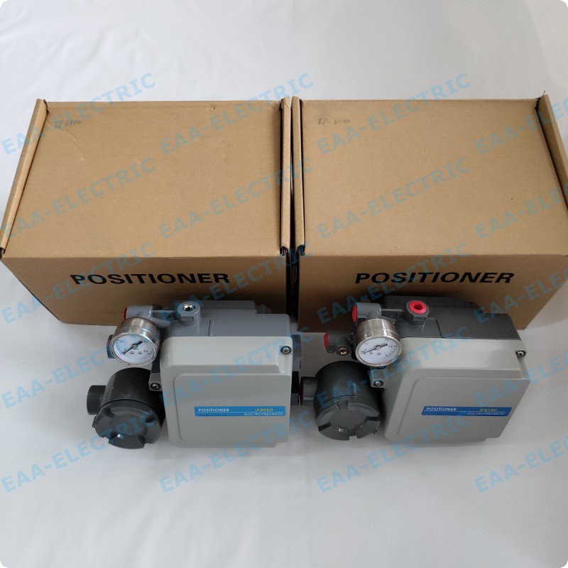
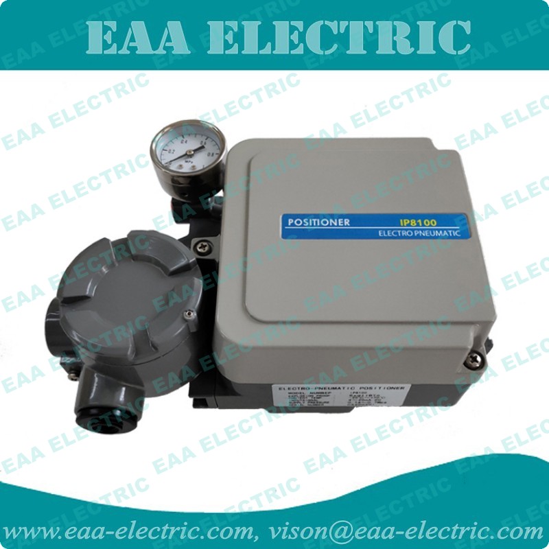
IP8000 Electro Pneumatic Valve Positioner
- OEM Support
- China Factory
- Best Price
- Quickest Delivery
- Product description: China leading and biggest professional Electro Pneumatic Valve Positioner and Electro Pneumatic Transducer OEM Manufacturer.
IP8000 Electro Pneumatic Valve Positioner-Data Sheet (PDF Download)
The IP8000 E/P positioner is more compact than the IP6000 with improved visibility of the pressure indicator. Other features include an improved enclosure protection IP65, interchangeable mounting, excellent shock and vibration performance, and a 1/2 split range available by simple span adjustment.
- Output current (4-20mADC) realizes remote position detecting (rotary type)
- Vibration resistance: No resonances 5 to 200Hz
- Dust resistance: Conforms to JIS F8007 IP65
- Pressure gauge O.D. 43
- Accessories include: Output restriction w/pilot valve, fork lever joint, compensation spring, w/external scale plate


- The electro valve positioner is the main accessory of the control valve. It takes the stem displacement signal as the input feedback measurement signal, and uses the controller output signal as the setting signal for comparison. When there is a deviation between the two, it changes its output to the actuator. The signal causes the actuator to act, establishing a one-to-one correspondence between the valve stem displacement times and the controller output signal. Therefore, the valve positioner constitutes a feedback control system that uses the displacement of the valve stem as the measurement signal and the output of the controller as the setting signal. The manipulated variable of the control system is the output signal from the valve positioner to the actuator.
The difference between the electro pneumatic positioner and the pneumatic valve positioner
The pneumatic valve positioner is made by the principle of torque, and when the signal pressure P1 of the bellows 2 is introduced, the main lever 3 is rotated around the fulcrum, so that the nozzle baffle 9 is close to the nozzle, the nozzle back pressure is performed by one direction amplifier 8 After amplifying, the pressure of the film chamber is introduced into the film chamber to move the valve stem downward. The feedback rod is rotated around the fulcrum, and the feedback cam is also rotated counterclockwise, and the secondary lever 4 is rotated by the roller, and the feedback spring is stretched, the spring to the main lever 3 is used in the bellows. When the force reaches the torque balance, the instrument reaches a balanced state. The valve position of the actuator is maintained on a certain opening, and a certain signal pressure corresponds to a certain valve position opening degree. The above mode is a positive effect. To change the mode, as long as the cam is flipped, a direction becomes b, that is, it can be. The so-called positive actor is the increase in signal pressure, and the output pressure also increases; the so-called reaction positioner is the increase in signal pressure, and the output pressure is reduced. A positive acting actuator can achieve the action of anti-action actuator as long as it is installed on the reaction positioner; in contrast, a reactionary actuator can achieve the action of the actual actuator as long as it installs the reaction positioner.
CATEGORIES
LATEST NEWS
- Introduction of Valve Positioner2016-01-09
- Action Principle of Valve Positioner2017-03-30
- Type of Valve Positioner2021-12-29
- New website online2021-12-29
- Working Principle and Basic Composition of Pneumatic Valve2021-12-31
CONTACT US
Contact: Vison Chan
Phone: 0086-15858563760
Tel: 0086-577-65165096
Email: vison.eaa@gmail.com , vison@eaa-electric.com
Add: EAA Central Industrial Zone,Wenzhou,Zhejiang Province,China

